K-Factor and Bend Allowance: Why Your Flat Patterns Come Back the Wrong Size
Why the 0.44 K-factor default in CAD silently breaks flat patterns on aluminum and stainless, with bend allowance math, error data, and a validation workflow.
A fabrication shop I worked with last month sent me five DXF files and a complaint: every bent part was coming off the press brake 1 to 4 mm shorter than the drawing. The nesting was fine. The cutting was fine. The bending operator was hitting his angles. The flat patterns themselves were wrong, by a margin that compounded with every additional bend.
The fix took ten minutes. Their CAD software was set to a K-factor of 0.44 — the default it ships with — and they were cutting 5052 aluminum, which has a K-factor closer to 0.33 at the radii they were forming. Every 90 degree bend introduced about 0.5 mm of error. A part with four bends ended up 2 mm short.
This is the most common preventable cause of “the nested parts are the wrong size” that I see. The DXF is a faithful flat pattern of whatever the CAD model unfolded to — and if the unfold math is wrong, the cut part is wrong before anyone touches the laser. This post covers what the K-factor actually represents, why the CAD default fails on common materials, and how to validate yours in twenty minutes with a strip of scrap and a caliper.
The short version
If you want the answer first: the K-factor is the ratio that locates the neutral axis inside a bend. For typical air-bend conditions with the inside radius equal to material thickness:
- Soft materials (annealed aluminum, soft brass): K ≈ 0.30 to 0.35
- Medium (mild steel, 6061 aluminum): K ≈ 0.40 to 0.45
- Hard (stainless, spring steel): K ≈ 0.45 to 0.50
CAD packages ship with 0.44 by default. That value only matches medium-hardness steel at moderate bend ratios. Use it on annealed aluminum and your flat pattern is roughly 0.5 mm long per bend. Use it on stainless and you are short by 0.1 to 0.2 mm per bend. Multi-bend parts compound the error linearly.
What the K-factor actually is
When you bend a piece of sheet metal, the outside of the bend stretches and the inside compresses. Somewhere between those surfaces is a fiber that does neither. That fiber is the neutral axis. The K-factor is the position of the neutral axis, measured from the inside of the bend, divided by the total material thickness:
K = t_neutral / TIf the neutral axis sat exactly in the middle of the material, K would equal 0.5. In practice it shifts toward the inside of the bend because the inside fibers resist compression more than the outside fibers resist tension. The amount it shifts depends on material strength, hardness, and the ratio of inside radius to thickness.
The bend allowance — the arc length of the neutral axis — is what your CAD software adds when it unfolds the bend into a flat pattern. The formula is:
BA = A × (π / 180) × (IR + K × T)where A is the bend angle in degrees, IR is the inside radius, K is the K-factor, and T is the material thickness. Get K wrong and BA is wrong by the same proportion.
Bend allowance vs. bend deduction
There are two ways to flatten a bend, and you need to know which one your CAD package is using because they produce identical results if K is correct and divergent results if it isn’t.
Bend allowance method: measure the flat lengths from each tangent line (where the bend starts), then add the bend allowance between them.
Bend deduction method: measure the outside dimensions of each flange, then subtract the bend deduction once per bend.
Bend deduction is:
BD = 2 × (IR + T) × tan(A/2) − BAThe two methods agree when K is correct. When K is wrong, they fail in opposite directions. If your inspection drawing is dimensioned outside-to-outside (the press brake operator’s default), bend deduction matches your shop’s workflow. If it is dimensioned inside-to-inside, bend allowance is the natural fit. Mismatch one to the other and the error stacks.
Steve Benson, writing in The Fabricator in 2017, called the default 0.446 K-factor a “fossilized” value: a compromise that fit one specific steel and tool combination from decades ago and got hard-coded into CAD packages everywhere. It works often enough that nobody notices, until you change material.
K-factor changes with the bend ratio, not just the material
The other half of the problem is that K is not a constant for a given material. It depends on the ratio of inside radius to thickness, often written IR/T. Tight bends pull the neutral axis further toward the inside. Generous bends let it relax back toward the middle.
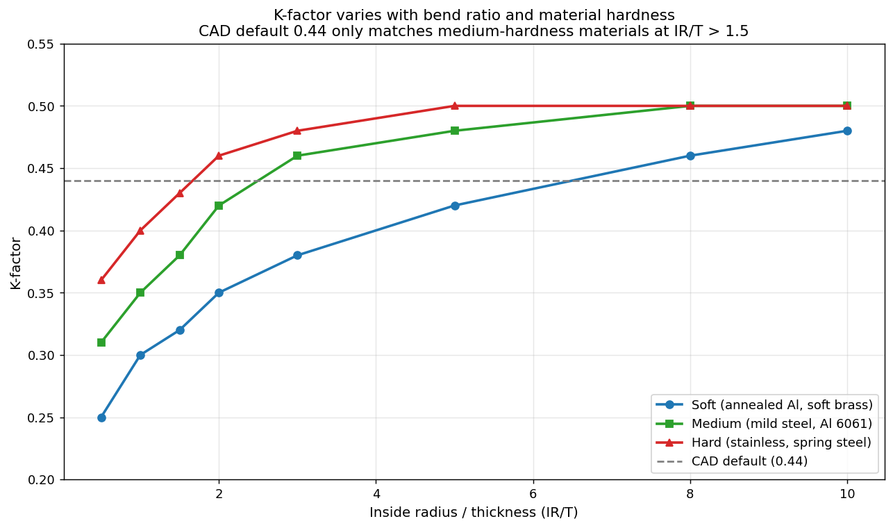
Below an IR/T ratio of about 1.0, K drops sharply for every material class. Above IR/T of 3, K asymptotes to roughly 0.50 regardless of hardness. The CAD default of 0.44 only sits near the right value for medium-hardness materials with bend ratios above 1.5. For an annealed aluminum bracket bent over a tight punch, the real K is closer to 0.30 and the default overshoots by 0.14 — which translates directly into wrong flat-pattern dimensions.
How the error compounds
For a single bend on thin material the error is often small enough to ignore, especially if your cut parts are getting deburred and dressed before assembly. The trouble starts on multi-bend parts.
The chart below shows the absolute error in flat-pattern length when the CAD default of K=0.44 is used for a 2 mm part with a 2 mm inside radius across five common materials. The error grows linearly with the number of bends.
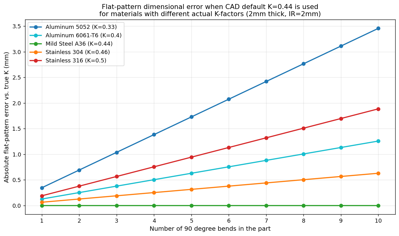
| Material | Actual K | Error per 90° bend | Error on 4-bend part |
|---|---|---|---|
| Aluminum 5052 | 0.33 | 0.35 mm | 1.4 mm |
| Aluminum 6061-T6 | 0.40 | 0.13 mm | 0.5 mm |
| Mild Steel A36 | 0.44 | 0.00 mm | 0.0 mm |
| Stainless 304 | 0.46 | 0.06 mm | 0.3 mm |
| Stainless 316 | 0.50 | 0.19 mm | 0.7 mm |
The mild steel row is the dishonest one. It is the only material where the CAD default happens to be right, and it is also the material the default was originally calibrated for. Every other material is paying a tax.
For a tolerance-loose bracket this might not matter. For a part that has to mate with a hole pattern, fit inside an enclosure, or stack flush against another piece, 1 to 2 mm of error is the difference between a part that ships and a part that gets remade.
How this shows up on the shop floor
From operators sending me their nesting jobs through Lapas, the wrong-flat-pattern problem surfaces in four characteristic ways:
-
A part fits in prototype but not in production. Prototypes get hand-fit. Production uses the DXF as-is. The error appears only at scale.
-
Holes near a bend drift away from the bend line. Bend allowance affects every flat dimension downstream of the bend, including hole positions. A hole drawn 25 mm from the bend on the flange may end up 26 mm or 24 mm away on the finished part.
-
Enclosure boxes don’t square up. Four bends on a tray, all with the same systematic error, accumulate until the top corners overlap or leave a gap. Operators blame the press brake, but the flat pattern was wrong before cutting.
-
The drawing dimensions don’t match the DXF. Shops working from drawings get bitten when the dimensioner and the CAD operator pick different unfold conventions. The DXF and the drawing then disagree on the flat length.
A twenty-minute validation workflow
Before trusting your CAD K-factor on a new material or a new tooling combination, measure it. The math is simple. The shop floor work is simple. Here is the workflow:
flowchart TD
    A[Cut a 200 mm x 50 mm strip\nfrom the material you'll use] --> B[Mark a bend line\nat the 100 mm midpoint]
    B --> C[Bend to 90 degrees\nwith your real tooling]
    C --> D[Measure both flange lengths\noutside-to-outside]
    D --> E[Sum the flange lengths\n= total outside dimension]
    E --> F[Subtract the 200 mm\noriginal flat length]
    F --> G[Result is the bend deduction\nfor this material and radius]
    G --> H[Back-solve for K\nusing the BD formula]
    H --> I[Save this K in your\nCAD material library]
The back-solve for K:
K = (2 × (IR + T) × tan(A/2) − BD) ÷ (A × π/180 × T) − IR/TFor a 90 degree bend on the 200 mm test strip, BD is just 200 − (flange1 + flange2). Plug in IR (your tooling punch radius), T (caliper-measured thickness), and BD, and you get a measured K-factor for your real shop conditions.
Repeat this for every material you cut more than occasionally. Aluminum 5052 in 2 mm, mild steel in 3 mm, stainless 304 in 1.5 mm — each gets its own measured K stored in a material library in your CAD. It is a one-day project for a shop that does five or six materials regularly, and it eliminates the most common source of “the part is the wrong size after bending” complaints.
Why this matters before nesting
Nesting software like Lapas takes the DXF as ground truth. If the DXF flat pattern is 2 mm short on a four-bend part, the nesting is perfect — perfectly placing a wrong-sized part on the sheet. The cost of the error doesn’t show up in utilization metrics. It shows up at assembly, when the part doesn’t fit.
The same is true for kerf compensation, which I have written about in Kerf Compensation in Nesting Software. The nester adjusts the outside profile to compensate for the cutting beam width. It cannot fix a flat pattern that started life with the wrong unfold math. Garbage in, precisely-nested garbage out.
If you are getting repeated mismatch complaints from your bending station, walk the flat pattern back to the CAD model. Check the K-factor. Verify which method (bend allowance or bend deduction) is being used. Cut a test strip. Twenty minutes of validation saves a week of mystery rework.
FAQ
What K-factor should I use for 1/8 inch aluminum?
For 3 mm 5052-H32 aluminum air-bent over a punch with radius equal to or slightly smaller than thickness, K is typically in the 0.30 to 0.35 range. For 6061-T6 at the same conditions, K runs 0.38 to 0.42. The CAD default of 0.44 is too high for both and will produce flat patterns that are slightly too long. Measure your own with a test strip before committing to a value.
Why does my K-factor change when I change the punch radius?
The K-factor is sensitive to the inside-radius-to-thickness ratio. Below an IR/T of about 1.0, the neutral axis shifts toward the inside of the bend (lower K). Above IR/T of 3, K stabilizes near 0.50. A shop that runs the same material with two different punch radii — say a small radius punch for tight bends and a larger one for sweep bends — needs two K-factor entries, not one.
Is bend allowance better than bend deduction, or the other way around?
Neither is mathematically better. They produce the same flat length if K is correct. Bend deduction is more natural if your inspection drawings are dimensioned outside-to-outside, which is the press brake operator’s default reference. Bend allowance is more natural if you are working from inside dimensions. Pick one and stick with it across CAD, drawing, and shop floor.
Does the K-factor matter for laser cutting tolerance, or only for bending?
The K-factor affects only the unfolded flat-pattern dimensions. The laser cuts whatever the DXF says. If the DXF is wrong by 1 mm, the cut part is wrong by 1 mm — but the laser itself is hitting its tolerance. Lasers usually hold ±0.1 mm or better. The flat-pattern error from a wrong K-factor is typically ten to twenty times larger than the cutting tolerance, so it dominates the final part error.
Why does my CAD software default to 0.44?
Historical inertia. 0.446 was the K-factor that worked for low-carbon A36 steel formed over a standard V-die in the 1960s and 70s, and it propagated into early CAD packages. Modern packages let you override it per material, but most shops never do. The default is mostly correct for medium-hardness steel and wrong for everything else.
Sources
- Benson, S. (2017). K-factors, Y-factors, and press brake bending precision. The Fabricator.
- Diehl, R. K-Factor charts and bend allowance formulas. Reference data published in standard sheet-metal design guides, summarised in SheetMetal.Me technical resources.
- Smlease Design. Sheet Metal K-Factor, Bend Allowance and Flat Length Calculations. Technical reference, updated 2025.