Pierce Time in Laser Cutting: Why Piercing Eats 30-50% of Your Cycle Time
Pierce time scales non-linearly with material thickness and can dominate laser cutting cycle time. Calculated pierce-to-cut ratios from 1-25 mm and how to cut piercing.
A shop owner asked me last month why his quoted cycle times kept coming in 30% short on a 10 mm mild steel job. He had the cut length right, the cut speed from the machine’s parameter table was correct, and the rapid traverse was barely a rounding error. The missing 30% was pierces. He had 180 pierces on the nest at roughly 2 seconds each, and his quoting spreadsheet treated piercing as an afterthought.
Pierce time is the period the laser spends drilling a hole through the sheet before it starts cutting along a contour. On thin sheet you barely notice it. On mid plate, between 5 mm and 15 mm, piercing accounts for 45 to 51% of the total cycle time for a typical production nest. That is not a quoting refinement, it is half your machine hours.
This post walks through what pierce time actually costs across material thicknesses, where the time goes during a single pierce, and the three pierce-reduction strategies that actually work in a production shop.
The Headline Number: Pierce Share by Thickness
I modeled a representative nest: 100 parts, 200 mm average perimeter per part, 2 pierces per part (one outer contour, one internal feature). Cut speeds and pierce times are published 6 kW fiber laser parameters for mild steel with oxygen assist. The job geometry is held constant. Only material thickness varies.
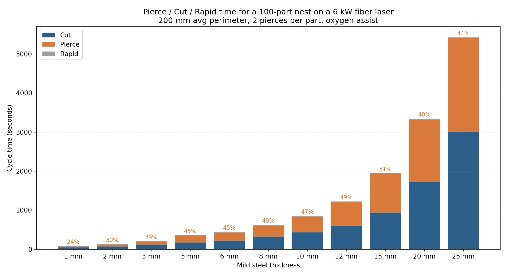
The table below is the same data in numeric form, which is more useful when you are reconciling a quote against actual machine logs.
| Thickness | Pierce time | Cut time | Rapid time | Total | Pierce share |
|---|---|---|---|---|---|
| 1 mm | 20 s | 40 s | 25 s | 85 s | 24% |
| 2 mm | 40 s | 67 s | 25 s | 132 s | 30% |
| 3 mm | 80 s | 100 s | 25 s | 205 s | 39% |
| 5 mm | 160 s | 171 s | 25 s | 356 s | 45% |
| 6 mm | 200 s | 218 s | 25 s | 443 s | 45% |
| 8 mm | 300 s | 300 s | 25 s | 625 s | 48% |
| 10 mm | 400 s | 429 s | 25 s | 854 s | 47% |
| 12 mm | 600 s | 600 s | 25 s | 1225 s | 49% |
| 15 mm | 1000 s | 923 s | 25 s | 1948 s | 51% |
| 20 mm | 1600 s | 1714 s | 25 s | 3339 s | 48% |
| 25 mm | 2400 s | 3000 s | 25 s | 5425 s | 44% |
Three things jump out.
At 1 mm the cycle is dominated by cut time and rapid traverse. Pierce is small enough that it cancels out in quoting noise. This is where shop estimating intuition was trained, and it is the wrong intuition for anything thicker than 3 mm.
From 5 mm upward, pierce and cut times converge. At 15 mm pierce overtakes cut. At 20 mm cut speed has dropped so far that cut time pulls ahead again, but pierce is still close to half.
The job geometry matters more than people credit. Holding everything else constant, doubling pierces from 200 to 400 on a 10 mm job adds 400 seconds, which is 47% more cycle time without cutting any additional metal. This is why nesting decisions like internal feature consolidation, common-line cutting, and edge starts move the cycle time needle so hard on mid plate.
Why Pierce Time Scales Non-Linearly
A pierce on 25 mm mild steel does not take 25 times longer than a pierce on 1 mm. It takes about 120 times longer. The relationship is closer to a power curve than a linear one.
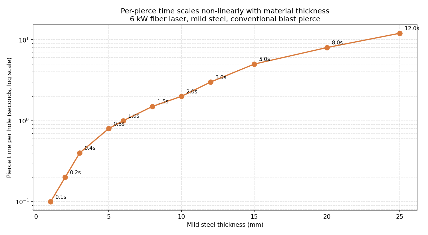
The reason is mechanical. Wandera and Kujanpää, in their 2010 study published in Proceedings of the Institution of Mechanical Engineers, Part B, modeled the melt removal rate for fiber laser cutting of thick stainless and showed that piercing on thick section is rate-limited by molten material ejection, not by absorbed beam power. As thickness grows, ejection from the bottom of the keyhole becomes harder. The laser has to maintain the keyhole long enough for the melt column to clear from below, which is a function of gas pressure, viscosity, and the melt column height itself. That height is the material thickness.
A standard “blast pierce” on 10 mm mild steel uses high oxygen pressure to blow the molten slug through the cut. The dwell required for full penetration is roughly 2 seconds. On 20 mm, that same blast pierce takes 8 seconds, partly because the slug is heavier and partly because the keyhole has to remain stable longer without collapsing.
This is the part operators miss: pierce time is not a tax you pay once per part, it is a tax you pay every time the head goes down. A small bracket with eight bolt holes piercing on 10 mm plate spends 18 seconds piercing before it starts contour cutting. The bracket itself may cut in 12 seconds.
Where a Single Pierce Goes
Inside one pierce event, the time breaks into three rough phases:
| Phase | Description | Share of pierce time |
|---|---|---|
| Beam-on / penetration | Laser melts and vaporizes through full thickness | 60-70% |
| Stabilization dwell | Keyhole stabilizes, melt column clears | 20-30% |
| Assist gas settle | Pressure ramps to cutting value, head moves to start | 5-10% |
The shop control you actually have is the pierce mode. Three modes dominate fiber laser production:
Blast pierce is the default. Full power, full oxygen pressure, drill straight through. Fastest mode for thicknesses up to about 10 mm. Above that, it blows molten material onto the lens cover and the surrounding sheet, which leaves a crater of slag around the pierce point that interferes with the lead-in. Most parameter tables on TRUMPF and Bystronic machines switch to a different mode above 10-12 mm.
Soft pierce (also called ramp pierce) starts at lower power and pulses up. Takes 1.5 to 2 times longer than blast pierce but leaves a much cleaner pierce point. Required for plates above roughly 12 mm and for materials where pierce-point spatter would damage adjacent parts.
Fly pierce keeps the head moving during the pierce instead of dwelling. The pierce happens along the lead-in path. Cuts pierce time by 30-50% on thin material because the dwell phase is hidden inside the lead-in motion. Does not work above about 6 mm.
A machine that has all three modes configured and a parameter table that picks the right one by thickness will be 10 to 20% faster on mid-plate work than the same machine running blast pierce on everything. This is firmware-level, not nesting-level, but it is worth checking before optimizing the nest.
What Actually Reduces Pierce Count
For a 10 mm mild steel job with 200 baseline pierces, here is what each strategy saves:
| Strategy | Pierces | Total cycle time | Saved |
|---|---|---|---|
| Baseline (one pierce per contour) | 200 | 854 s | — |
| Common-line cutting | 110 | 669 s | 22% |
| Edge starts on outer contours | 150 | 754 s | 12% |
| Both combined | 80 | ~575 s | ~33% |
These numbers are from the same model run with realistic geometry assumptions. The breakdown:
Common-line cutting shares one cut edge between two parts. A pierce that would have separated two adjacent rectangles becomes a single cut through their shared boundary. Each shared edge saves one pierce. On rectangular grid nests, this can remove up to 85% of pierces; on true-shape nesting it is closer to 40-50%. My earlier post on common line cutting walks through the geometry and the consumable cost effect.
Edge starts begin the cut from the existing sheet edge instead of piercing through. They only work for outer contours of parts that sit on or near the sheet boundary. In a typical nest, 30-50% of parts touch the sheet edge after the nesting solver has done its job, so the pierce reduction is bounded by what fits along the perimeter.
Internal feature consolidation is the quietest one and the one most operators miss. If a part has four 5 mm holes that could be replaced by one 8 mm slot, that change removes three pierces. On a 100-part nest where the design tolerates it, this is a 300-pierce reduction. The constraint here is DFM negotiation with the customer, not the machine.
A Workflow for Diagnosing Pierce Overhead
flowchart TD
A[Actual cycle exceeds quote by >15%] --> B[Pull pierce count from G-code]
B --> C{Pierces × pierce time<br/>> 30% of total?}
C -->|No| D[Look elsewhere:<br/>rapid, dwell, parameters]
C -->|Yes| E{Material above 5 mm?}
E -->|No| F[Check pierce mode:<br/>can fly pierce apply?]
E -->|Yes| G{Parts share edges<br/>or repeat geometry?}
G -->|Yes| H[Apply common-line cutting]
G -->|No| I{Parts on sheet boundary?}
I -->|Yes| J[Enable edge starts]
I -->|No| K[Consolidate internal features<br/>in DFM review]Pierces are visible in any G-code. M03 / M05 or laser-on / laser-off pairs each represent one pierce-and-cut sequence. Counting them takes a minute and exposes whether the quote model needs adjustment or the nest needs to change.
The shop owner I mentioned at the start fixed his quoting in two steps. First, he added pierce count as a quoted variable, separate from cut length. Second, he turned on common-line cutting for the bracket family that ran most often, which cut his pierces in half and his cycle time by about 20%. The quoting accuracy went from “off by 30%” to within 5%, which mattered more for his margins than the cycle time gain itself.
FAQ
How long does a typical laser pierce take?
For 6 kW fiber on mild steel: 0.1 s at 1 mm, around 1 s at 6 mm, 2 s at 10 mm, 8 s at 20 mm, and 12+ s at 25 mm. Stainless steel with nitrogen runs about 1.5 to 2 times longer for the same thickness. Aluminium runs about 1.5 times longer because of reflectivity.
Why does pierce time matter more on thick material?
Two reasons. Per-pierce time grows non-linearly with thickness, roughly as a power function, so each pierce on 20 mm plate costs about 4 times as much as on 10 mm. And cut speed drops, which means a job at 20 mm takes longer overall, so the absolute minutes lost to piercing become a bigger budget line.
Can I reduce pierce time without changing my nesting software?
Yes, by checking your machine’s pierce mode parameter table. Many shops run blast pierce on every thickness because it is the default. Switching to fly pierce on thin material can save 30-50% per pierce; switching to soft pierce on thick material gives slower individual pierces but eliminates blow-back damage that requires manual cleanup or rework.
How do I count pierces on a finished nest?
In the G-code, count laser-on commands (typically M03 or a brand-specific pierce command). Most nesting and CAM software also reports pierce count on the nest summary screen alongside cut length and estimated cycle time. If your software does not, that is the first thing to ask about; pierce count is one of the two numbers that drives cycle time on mid plate.
Is common-line cutting the same thing as edge starts?
No. Common-line cutting shares a cut edge between two adjacent parts in the nest, eliminating one pierce per shared boundary. Edge starts begin a single part’s cut at the existing sheet boundary, eliminating only that part’s outer-contour pierce. Both reduce pierce count; they target different pierces.